BW-Fixators®
Series RK:
When you need to align and (re-)adjust your machine most exact, the series RK is the right choice.
BW-Fixators® of series RK are easy to operate and precise in adjustment. The time for the alignment of e.g. a lathe will be reduced significant. If the machines needs to be re-adjusted because of foundation shifting or shrinkage, it can be done simply and fast. With a wide range of accessory and anchoring methods the series RK covers nearly any application.
BW-Fixators® of series RK fulfil all requierments, conditions and properties appointed by the industry. All load-bearing and moveable parts including guiding surfaces are made from high-quality lamellar grey cast iron. To ensure the smooth handling of this parts over years, they are treated with molybdenum disulfide.
Downloads
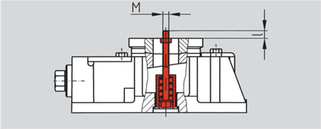
Machine alignment with BW-Fixators®:![]()
![]()
![]()
![]()
Dimensions of series RK
GA Basic Unit
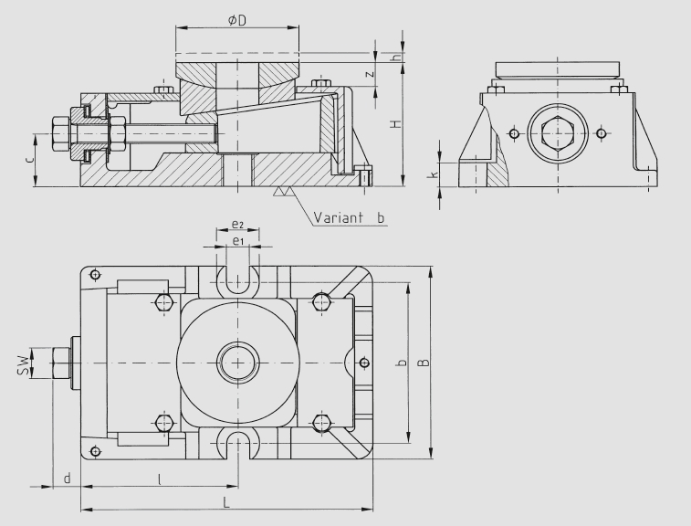
| Size | L | B | H* | ØD | SW | d | c | z | h | l | b | e1 | e2 | k |
|---|---|---|---|---|---|---|---|---|---|---|---|---|---|---|
| I | 175 | 105 | 55 | 60 | 19 | 16 | 21 | 13 | 5 | 92 | 90 | 14 | 26 | 12 |
| II | 178 | 120 | 75 | 75 | 19 | 15 | 31 | 15 | 5 | 96 | 100 | 14 | 26 | 13 |
| III | 220 | 150 | 95 | 90 | 24 | 22 | 40 | 17 | 6 | 118 | 130 | 18 | 32 | 22 |
| IV | 275 | 180 | 115 | 110 | 30 | 24 | 49 | 17 | 8 | 142 | 160 | 24 | 38 | 24 |
| V | 345 | 230 | 135 | 150 | 36 | 34 | 58 | 20 | 10 | 180 | 205 | 28 | 46 | 34 |
| VI | 420 | 270 | 165 | 200 | 46 | 34 | 67 | 32 | 13 | 230 | 245 | 28 | 46 | 31 |
*Height with machined bottom (Variant b)
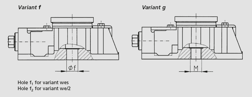
| Size | Øf1 | Øf2 | g |
|---|---|---|---|
| I | 17 | 19 | M12 |
| II | 21 | 25 | M20 |
| III | 25 | 31 | M24 |
| IV | 31 | 37 | M30 |
| V (M 36) | 37 | 44 | M36 |
| V (M 42) | 44 | - | - |
| VI | 58 | - | M42 |
Technical Datas for Series RK
| Size | Dim | RK I | RK II | RK III | RK IV | RK V | RK VI | |
|---|---|---|---|---|---|---|---|---|
| Permissible maximum load ¹) | N | 90.000 | 120.000 | 240.000 | 360.000 | 700.000 | 1.200.000 | |
| Recommended machine dead weight ²) | N | 10.000 | 20.000 | 40.000 | 60.000 | 120.000 | 200.000 | |
| Spring constant in operation range ³) | N/µm | 2.000 | 4.500 | 8.000 | 10.000 | 14.000 | 18.000 | |
| Torque at adjusting screw | Specific- | Nm / 10³ kg | 3 | 3 | 4 | 4,5 | 5,5 | 7 |
| Maximum- | Nm | 27 | 36 | 96 | 160 | 385 | 700 | |
| Security- | Nm | 2,5-5 | 2,5-5 | 3,5-7 | 4-8 | 5-10 | 20 | |
| Vertical Adjustment per screw turn | mm | 0,25 | 0,25 | 0,29 | 0,35 | 0,43 | 0,5 | |
| Weight of basic unit | kg | 4 | 5,5 | 11,5 | 21 | 42 | 70 | |
1) BW-Fixators® are adjustable up to this load.
2) This is the standard factor for the determination of the BW-Fixator® size.
3) Found by applying a changing load equal to the recommended proportional machine load. The operating
range will be covered when the machine has beenlevelled and bound down with the anchor bolts.
Formula for calculating the Resilience of BW-Fixators® Serie RK
![]()
Note: The total of the forces a – e exerted must not exceed the permissible maximum load
a) Proportional machine load
b) Tensile force exerted by anchor bolt
c) Dynamic forces
d) Changing loads (moving machine parts or workpieces)
e) Forces counteracting moments
Determination of BW-Fixator® size
The proportinal machine load recommended is a function of the net weight of the machine devided by the number of support points (BW-Fixators®). For machinery with sizable variations in partial weight, it is the heaviest machine load that has to be devided by the number of bearing points and the resulting BW-Fixator® size has to be used everywhere under the machine.
Anchor bolts and studs
wes
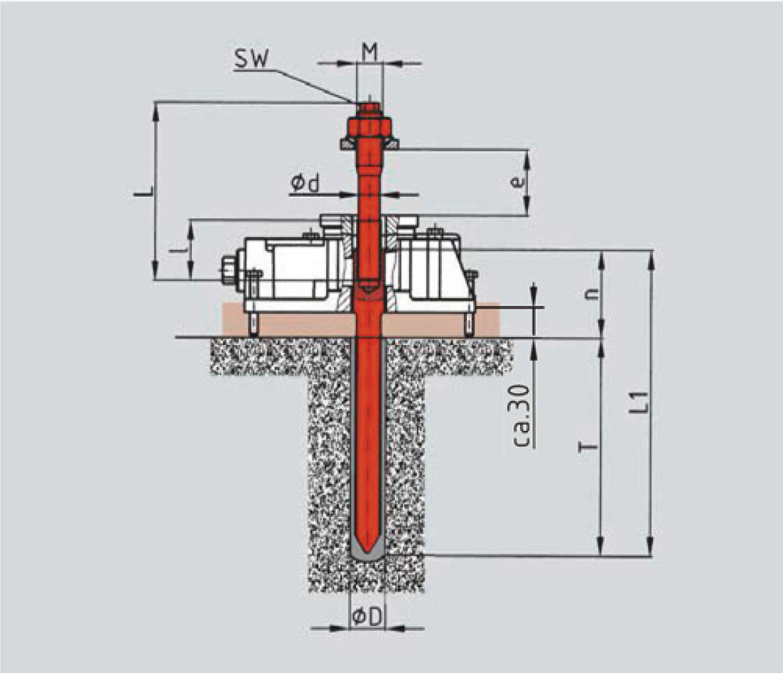
Anchor bolt for direct connection of the machine to the foundation
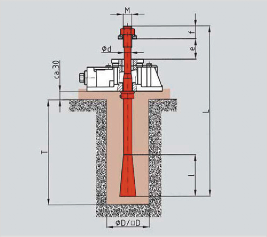
| e | Foundations | Clamping force | ||||||||||||
|---|---|---|---|---|---|---|---|---|---|---|---|---|---|---|
| RK | M | L | l | f | Ød | von | bis | D | T | max. N | ||||
| I | M16 | 330 | 90 | 30 | 13 | 20 | 60 | 70 | 230 | 53.000 | ||||
| II | M20 | 400 | 100 | 40 | 16 | 20 | 90 | 80 | 270 | 81.000 | ||||
| III | M24 | 500 | 135 | 50 | 19 | 30 | 100 | 100 | 340 | 115.000 | ||||
| IV | M30 | 600 | 150 | 55 | 24 | 35 | 135 | 120 | 410 | 182.000 | ||||
| V | M36 | 800 | 180 | 65 | 29 | 40 | 150 | 150 | 570 | 265.000 | ||||
| M42 | 1.000 | 260 | 75 | 35 | 40 | 200 | 170 | 760 | 385.000 | |||||
| VI | More information on request. | |||||||||||||
we/2
Split anchor bolt for direct connection of the machine to the foundation
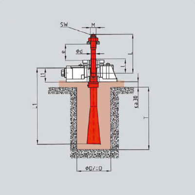
| short | e | long | e | Foundations | Clamping force | |||||||||||||||
|---|---|---|---|---|---|---|---|---|---|---|---|---|---|---|---|---|---|---|---|---|
| RK | M | L1 | l1 | Ød | SW | L | l | von | bis | L | l | von | bis | D | T | max. N | ||||
| I | M16 | 190 | 39 | 13 | 10 | 130 | 55 | 20 | 55 | 155 | 60 | 60 | 80 | 80 | 150 | 53.000 | ||||
| II | M20 | 275 | 48 | 16 | 13 | 140 | 50 | 20 | 50 | 190 | 80 | 55 | 100 | 100 | 220 | 81.000 | ||||
| III | M24 | 360 | 63 | 19 | 17 | 165 | 60 | 30 | 60 | 225 | 90 | 65 | 120 | 120 | 290 | 115.000 | ||||
| IV | M30 | 450 | 85 | 24 | 19 | 190 | 70 | 35 | 70 | 255 | 110 | 75 | 135 | 150 | 360 | 182.000 | ||||
| V | M36 | 600 | 105 | 29 | 24 | 220 | 80 | 40 | 80 | 275 | 120 | 85 | 135 | 170 | 500 | 265.000 | ||||
| VI | More information on request. | |||||||||||||||||||
Note: Specify dimension „e“ (thickness of machine leg) in your order
due
Resin anchor
(Capsule and stud)

| e | Hole | Clamping force | |||||||||||
|---|---|---|---|---|---|---|---|---|---|---|---|---|---|
| RK | M | L | SW | f | von | bis | ØD | T | max. N* | ||||
| I | M16 | 300 | 10 | 35 | 20 | 60 | 18 | 125 | 15.000 | ||||
| II | M20 | 400 | 13 | 40 | 20 | 90 | 25 | 170 | 27.000 | ||||
| III | M24 | 450 | 17 | 50 | 20 | 70 | 28 | 210 | 37.000 | ||||
*Concrete ≥ B 25
due/2
Split Resin anchor
(Capsule and split stud)
| short | e | long | e | Hole | Clamping force* | ||||||||||||||||
|---|---|---|---|---|---|---|---|---|---|---|---|---|---|---|---|---|---|---|---|---|---|
| RK | M | Ød | SW | L | l | von | bis | L | l | von | bis | L1 | n | ØD | T | max. N | |||||
| I | M16 | 13 | 10 | 130 | 55 | 20 | 55 | 155 | 60 | 60 | 80 | 185 | 60 | 18 | 125 | 15.000 | |||||
| II | M20 | 16 | 13 | 140 | 50 | 20 | 50 | 190 | 80 | 55 | 100 | 240 | 70 | 25 | 170 | 27.000 | |||||
| III | M24 | 19 | 17 | 165 | 60 | 30 | 60 | 225 | 120 | 65 | 120 | 290 | 80 | 28 | 210 | 37.000 | |||||
*Concrete ≥ B 25
Note: Specify dimension „e“ (thickness of machine leg) in your order
ste
Short or long stud bolt for attaching the machine to the BW-Fixator®
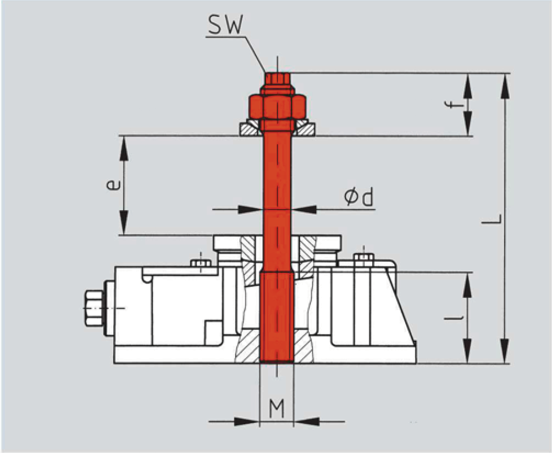
| short | e | long | e | Clamping force | |||||||||||||||
|---|---|---|---|---|---|---|---|---|---|---|---|---|---|---|---|---|---|---|---|
| RK | M | Ød | SW | f | L | l | von | bis | L | l | von | bis | max. N | ||||||
| I | M12 | - | - | - | 130 | - | 20 | 40 | 160 | - | 40 | 70 | 32.000 | ||||||
| II | M20 | 16 | 13 | 40 | 175 | 55 | 20 | 55 | 205 | 55 | 50 | 85 | 81.000 | ||||||
| III | M24 | 19 | 17 | 50 | 215 | 70 | 20 | 70 | 260 | 70 | 65 | 115 | 115.000 | ||||||
| IV | M30 | 24 | 19 | 55 | 260 | 85 | 30 | 85 | 310 | 85 | 80 | 135 | 182.000 | ||||||
| V | M36 | 29 | 24 | 65 | 315 | 105 | 40 | 105 | 360 | 105 | 100 | 150 | 265.000 | ||||||
| VI | More information on request. | ||||||||||||||||||
Note: Specify dimension „e“ (thickness of machine leg) in your order.
ste/2
Short or long split stud bolt for attaching the machine to the BW-Fixator®
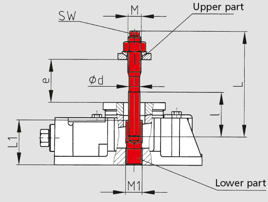
| short | e | long | e | Clamping force | ||||||||||||||||
|---|---|---|---|---|---|---|---|---|---|---|---|---|---|---|---|---|---|---|---|---|
| RK | M | Ød | SW | L | l | von | bis | L | l | von | bis | L1 | M1 | max. N | ||||||
| II | M16 | 13 | 10 | 130 | 55 | 20 | 60 | 155 | 60 | 65 | 85 | 55 | M20 | 53.000 | ||||||
| III | M20 | 16 | 13 | 140 | 50 | 20 | 50 | 190 | 80 | 55 | 100 | 70 | M24 | 81.000 | ||||||
| IV | M24 | 19 | 17 | 165 | 60 | 30 | 60 | 225 | 90 | 65 | 120 | 85 | M30 | 115.000 | ||||||
| V | M30 | 24 | 19 | 190 | 70 | 40 | 70 | 255 | 110 | 75 | 135 | 105 | M36 | 182.000 | ||||||
Note: Specify dimension „e“ (thickness of machine leg) in your order.
c
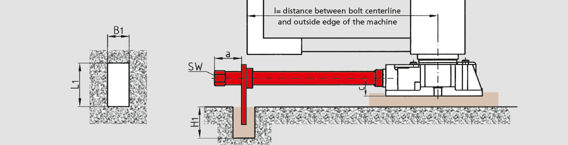
Side anchor bolts for connecting BW-Fixator® to the foundation
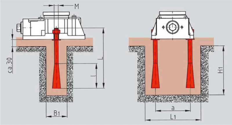
| Foundations | Clamping force | |||||||||||
|---|---|---|---|---|---|---|---|---|---|---|---|---|
| RK | M | L | l | a | L1 | B1 | H1 | max. N | ||||
| I | M12 | 150 | 70 | 90 | 140 | 60 | 140 | 65.000 | ||||
| II | M12 | 150 | 70 | 100 | 160 | 60 | 140 | 65.000 | ||||
| III | M16 | 250 | 90 | 130 | 200 | 70 | 240 | 120.000 | ||||
| IV | M20 | 300 | 100 | 160 | 240 | 80 | 290 | 190.000 | ||||
| V | M24 | 350 | 135 | 205 | 305 | 100 | 350 | 275.000 | ||||
Other applications
p
Spherical washer set for non-parallel bearing surfaces
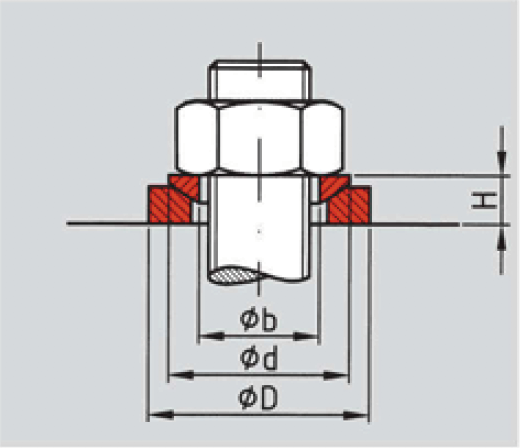
| RK | ØD | H | Ød | Øb |
|---|---|---|---|---|
| I (M12) | 40 | 9 | 30 | 13 |
| I (M16) | 40 | 9 | 30 | 17 |
| II | 44 | 10 | 36 | 21 |
| III | 56 | 13 | 44 | 25 |
| IV | 68 | 16 | 56 | 31 |
| V (M36) | 78 | 20 | 68 | 37 |
| V (M42) | 100 | 26 | 90 | 44 |
r
Large spherical washer set for non-parallel bearing surfaces
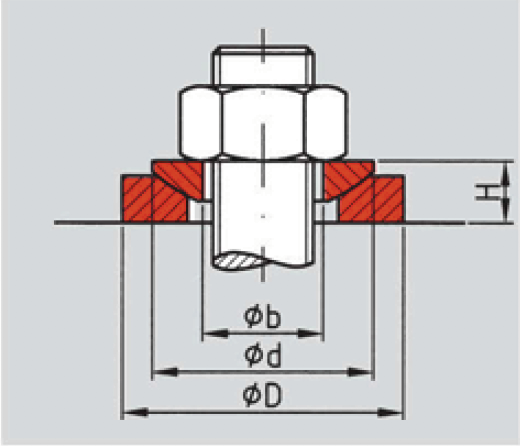
| RK | ØD | H | Ød | Øb |
|---|---|---|---|---|
| I | 44 | 10 | 36 | 17 |
| II | 56 | 13 | 44 | 21 |
| III | 68 | 16 | 56 | 25 |
| IV | 80 | 16 | 56 | 31 |
| V (M36) | 100 | 20 | 68 | 37 |
| V (M42) | 125 | 26 | 90 | 44 |
z
Foam centering bushing for concentric location of anchor bolts in the machine foot holes
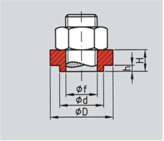
| RK | Øf | ØD | H | Ød | h |
|---|---|---|---|---|---|
| I | 16,2 | 32 | 13 | 22 | 4 |
| II | 20,2 | 40 | 14 | 28 | 4 |
| III | 24,2 | 44 | 18 | 32 | 5 |
| IV | 30,2 | 54 | 21 | 42 | 5 |
| V (M36) | 36,3 | 60 | 26 | 45 | 6 |
| V (M42) | 42,5 | 70 | 32 | 56 | 6 |
le
Extended set screw on BW-Fixator® arranged inwards of the machine side
| Minimum | Foundations | |||||||||
|---|---|---|---|---|---|---|---|---|---|---|
| RK | a | c | SW | length l | Tube | L1 | B1 | H1 | ||
| I | 50 | 23 | 22 | 140 | 24x4 | 80 | 40 | 70 | ||
| II | 50 | 33 | 22 | 140 | 24x4 | 80 | 40 | 70 | ||
| III | 50 | 42 | 22 | 170 | 24x4 | 80 | 40 | 90 | ||
| IV | 50 | 51 | 32 | 200 | 38x5 | 100 | 50 | 100 | ||
| V | 50 | 60 | 32 | 250 | 38x5 | 100 | 50 | 110 | ||
led
Extended set screw on BW-Fixator® arranged inwards of the machine side
Fixing with Eye screw

| Minimum | led | led-l | ||||||||||
|---|---|---|---|---|---|---|---|---|---|---|---|---|
| RK | a | c | SW | length l | Tube | min | max | Umax | max | Umax | ØD | T |
| I | 50 | 23 | 22 | 140 | 24x4 | 25 | 80 | ≤60 | 120 | ≤100 | 14 | 120 |
| II | 50 | 33 | 22 | 140 | 24x4 | 25 | 80 | ≤50 | 120 | ≤90 | 14 | 120 |
| III | 50 | 42 | 22 | 170 | 24x4 | 25 | 80 | ≤40 | 120 | ≤80 | 14 | 120 |
| IV | 50 | 51 | 32 | 200 | 38x5 | 40 | 120 | ≤70 | 14 | 120 | ||
| V | 50 | 60 | 32 | 250 | 38x5 | 40 | 120 | ≤60 | 14 | 120 | ||
les
Extended set screw on flush-mounted BW-Fixator® arranged inwards of the machine side
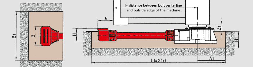
| Minimum | Foundations | ||||||||||
|---|---|---|---|---|---|---|---|---|---|---|---|
| RK | a | B | H | length l | A1 | Z1 | B1 | H1 | X1 | ||
| I | 61 | 81 | 47 | 140 | 130 | 20 | 160 | 70 | 230 | ||
| II | 65 | 92 | 59 | 140 | 140 | 25 | 200 | 80 | 240 | ||
| III | 72 | 92 | 59 | 180 | 160 | 30 | 250 | 100 | 270 | ||
| IV | 75 | 136 | 96 | 240 | 200 | 35 | 300 | 120 | 320 | ||
| V | 80 | 136 | 96 | 275 | 230 | 40 | 330 | 140 | 370 | ||
d
Lateral adjuster for adjusting machine location
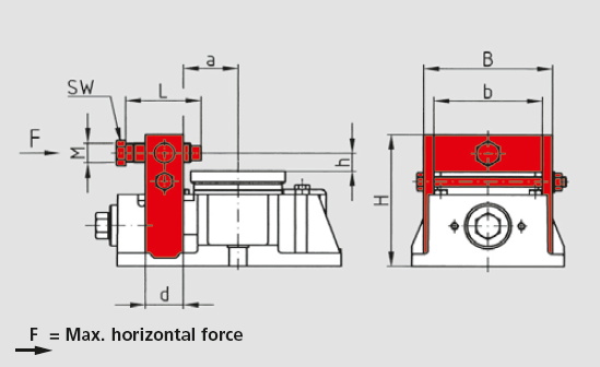
| F | |||||||||||
|---|---|---|---|---|---|---|---|---|---|---|---|
| RK | M | L | SW | H | B | b | d | a | h | N | |
| I | M12 | 50 | 17 | 83 | 86 | 70 | 25 | 40 | 15 | 20000 | |
| II | M16 | 60 | 19 | 106 | 102 | 86 | 30 | 43 | 16 | 25000 | |
| III | M16 | 60 | 19 | 129 | 129 | 109 | 35 | 55 | 16 | 35000 | |
| IV | M20 | 70 | 24 | 160 | 150 | 130 | 40 | 70 | 20 | 40000 | |
| V | M24 | 80 | 30 | 192 | 199 | 175 | 45 | 90 | 24 | 60000 |
dz
Offset lateral adjuster for adjusting machine location

| F | |||||||||||
|---|---|---|---|---|---|---|---|---|---|---|---|
| RK | M | L | SW | H | B | b | d | a | h | N | |
| I | M12 | 50 | 17 | 83 | 102 | 86 | 25 | 57 | 15 | 20000 | |
| II | M16 | 60 | 19 | 106 | 118 | 102 | 30 | 65 | 16 | 25000 | |
| III | M16 | 60 | 19 | 129 | 149 | 129 | 35 | 80 | 16 | 35000 | |
| IV | M20 | 70 | 24 | 160 | 170 | 150 | 40 | 100 | 20 | 40000 | |
| V | M24 | 80 | 30 | 192 | 223 | 199 | 45 | 123 | 24 | 60000 |
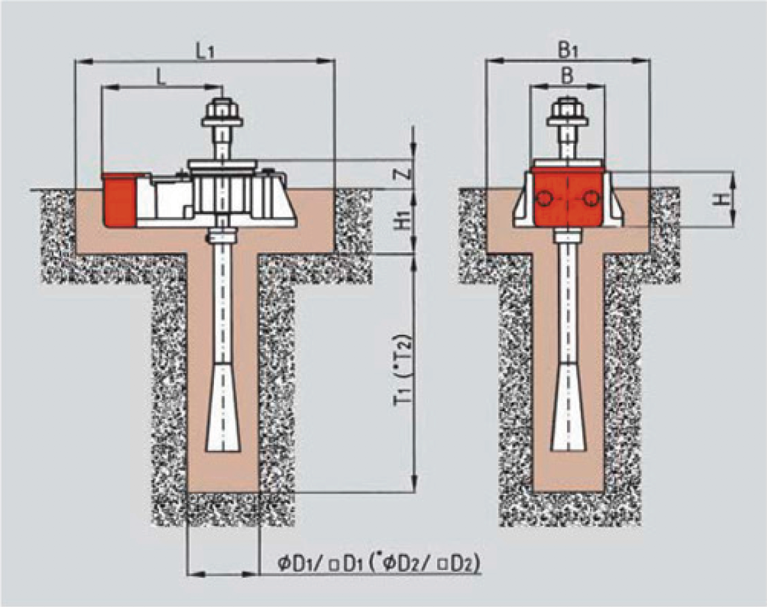
m
Set screw guard on flush mounted BW-Fixator®
Foundations at combination of variants m and wes
| Fundament | *Ausführung 2 | ||||||||||||||
|---|---|---|---|---|---|---|---|---|---|---|---|---|---|---|---|
| RK | L | B | H | Z | L1 | H1 | B1 | D1 | T1 | D2 | T2 | ||||
| I | 129 | 81 | 47 | 20 | 310 | 70 | 160 | 70 | 230 | - | - | ||||
| II | 138 | 92 | 59 | 25 | 310 | 80 | 200 | 80 | 270 | 100 | 360 | ||||
| III | 160 | 92 | 59 | 30 | 380 | 100 | 250 | 100 | 340 | 120 | 430 | ||||
| IV | 206 | 136 | 96 | 35 | 450 | 120 | 300 | 120 | 410 | 150 | 590 | ||||
| V | 245 | 136 | 96 | 40 | 550 | 140 | 330 | 150 | 570 | 170 | 760 | ||||
*Foundations 2 in connection with the next size of anchor bolts
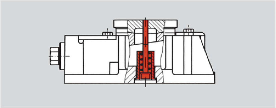
mon
Locking system for the spherical bearing plate
frot
Connection for mobile arrangement
| RK | M | l |
|---|---|---|
| I | 6 | 8 |
| II | 6 | 8 |
| III | 8 | 8 |
| IV | 8 | 12 |
| V | 12 | 12 |