BW-Fixators® – Series S:
The series S has been developed especially for big tooling plates and tables because with most of them the alignment from the side is not possible. The leveling elements are only accessible from the top. This is why the series S is adjustable from above, the adjustemt can be done via the fixing srew. Series S has a setting range from 8 mm (size S I) to 20 mm (size S V).
BW-Fixators ® series S are easy to operate and to adjust with precision. The time for the alignment will be reduced significant. If the machines needs to be re-adjusted because of foundation shifting or shrinkage, it can be done simply and fast. With it’s accessory and anchoring methods the series S covers a wide range of applications.
Matching with the recesses of series S the holes can be closed with our series D.
Downloads
Machine alignment with BW-Fixators®:![]()
![]()
![]()
![]()
Dimensions of series S
GA Basic Unit
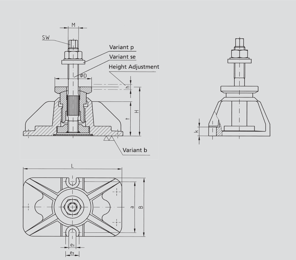
| Size | M | L | B | H | ØD | h | SW | t | a | k | e1 | e2 |
|---|---|---|---|---|---|---|---|---|---|---|---|---|
| I | M16x1,5 | 168 | 105 | 80 | 57 | 8 | 12 | 60 | 88 | 16 | 12 | 22 |
| II | M20x1,5 | 190 | 115 | 95 | 70 | 10 | 15 | 68 | 100 | 20 | 14 | 26 |
| III | M24x1,5 | 220 | 140 | 113 | 82 | 12 | 19 | 83 | 120 | 25 | 18 | 32 |
| IV | M30x1,5 | 280 | 185 | 140 | 100 | 16 | 24 | 97 | 150 | 32 | 24 | 38 |
| V | M36x1,5 | 330 | 225 | 166 | 122 | 20 | 30 | 120 | 180 | 38 | 28 | 46 |
Technical Data for series S
| Size | Dim | S I | S II | S III | S IV | S V | |
|---|---|---|---|---|---|---|---|
| Permissible maximum load | N | 90.000 | 120.000 | 240.000 | 360.000 | 600.000 | |
| Recommended machine dead weight ¹) | N | 10.000 | 20.000 | 40.000 | 60.000 | 100.000 | |
| Spring constant in operation range ²) | N/µm | 1.500 | 2.000 | 2.500 | 3.000 | 4.000 | |
| Torque at adjusting screw | Specific- | Nm / 10³ kg | 35 | 45 | 50 | 60 | 70 |
| Maximum- | Nm | 120 | 240 | 480 | 960 | 2.050 | |
| Max. Torque at the clamping nut | Nm | 60 | 120 | 240 | 480 | 960 | |
| Weight of basic unit | kg | 3,25 | 5,10 | 8,40 | 15,30 | 27,60 | |
| Vertical adjustment per screw turn | all sizes 2 mm | ||||||
2) The operating range will be covered when the floor plate has been levelled and bound
down with the anchor bolts.
Formula for calculating the Resilience of BW-Fixators® Serie S
![]()
Note:
The total of the forces a – e exerted must not exceed the permissible maximum load.
a) Proportional machine load
b) Tensile force exerted by anchor bolt
c) Dynamic forces
d) Changing loads (moving machine parts or workpieces)
e) Forces counteracting moments
Adjusting and anchor bolts
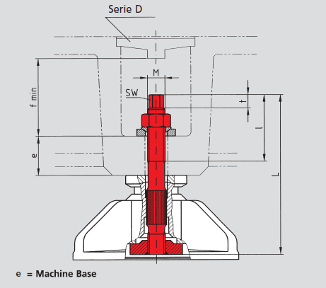
se
High tensile hold-down and adjusting bolt
| short | e | long | e | Clamping force | |||||||||||||
|---|---|---|---|---|---|---|---|---|---|---|---|---|---|---|---|---|---|
| S | M | SW | t | f | L | l | von | bis | L | l | von | bis | max. N | ||||
| I | M16x1,5 | 12 | 12 | 80 | 170 | 65 | 20 | 40 | 190 | 65 | 40 | 60 | 53.000 | ||||
| II | M20x1,5 | 15 | 15 | 90 | 180 | 75 | 20 | 40 | 200 | 75 | 40 | 60 | 81.000 | ||||
| III | M24x1,5 | 19 | 19 | 105 | 235 | 90 | 35 | 60 | 255 | 90 | 60 | 80 | 115.000 | ||||
| IV | M30x1,5 | 24 | 24 | 125 | 310 | 110 | 60 | 90 | - | - | - | - | 182.000 | ||||
| V | M36x1,5 | 30 | 30 | 160 | 380 | 130 | 70 | 110 | - | - | - | - | 265.000 | ||||

sew
Center anchor hold-down stud
| Foundations | Clamping Force | |||||||||
|---|---|---|---|---|---|---|---|---|---|---|
| S | M | SW | L | l | Ød | ØD | T | max. N | ||
| I | M16x1,5 | 12 | 150 | 90 | 16 | 70 | 180 | 53.000 | ||
| II | M20x1,5 | 15 | 200 | 100 | 20 | 80 | 250 | 81.000 | ||
| III | M24x1,5 | 19 | 270 | 135 | 24 | 100 | 320 | 115.000 | ||
| IV | M30x1,5 | 24 | 320 | 150 | 30 | 120 | 380 | 182.000 | ||
| V | M36x1,5 | 30 | 450 | 180 | 36 | 150 | 520 | 265.000 | ||
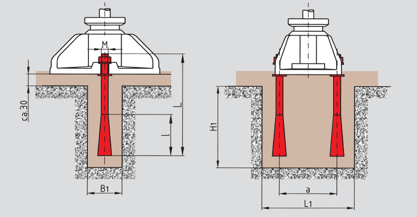
c
Two side anchor bolts for securing the BW-Fixator® to the foundation
| Foundations | Clamping Force | |||||||||
|---|---|---|---|---|---|---|---|---|---|---|
| S | M | L | l | a | L1 | B1 | H1 | max. N | ||
| I | M10 | 125 | 55 | 88 | 135 | 50 | 120 | 45.000 | ||
| II | M12 | 150 | 70 | 100 | 160 | 60 | 140 | 65.000 | ||
| III | M16 | 250 | 90 | 120 | 200 | 70 | 240 | 120.000 | ||
| IV | M20 | 300 | 100 | 150 | 250 | 80 | 290 | 190.000 | ||
| V | M24 | 350 | 135 | 180 | 350 | 100 | 350 | 275.000 | ||
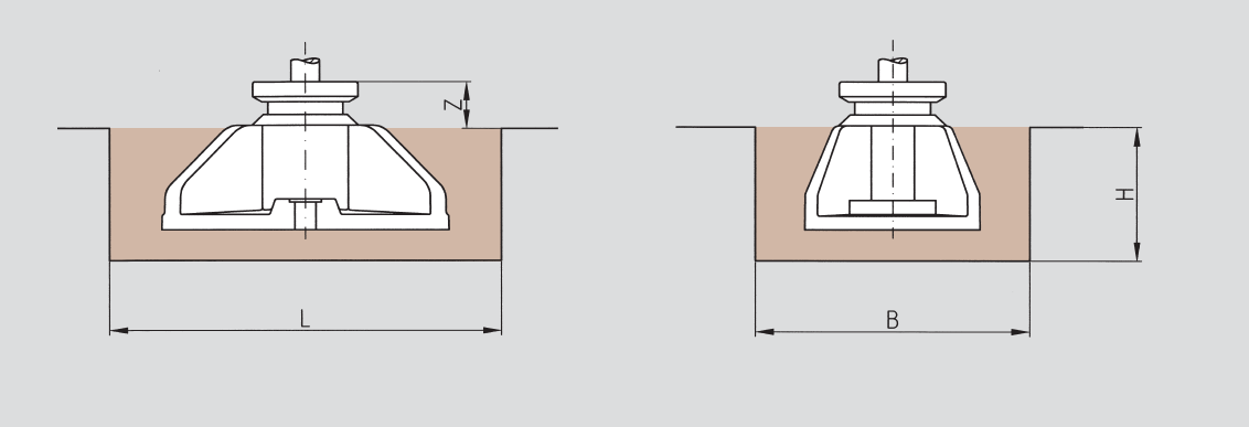
| Foundations | ||||
|---|---|---|---|---|
| S | Z | L | B | H |
| I | 30 | 300 | 160 | 100 |
| II | 35 | 330 | 200 | 110 |
| III | 40 | 350 | 240 | 140 |
| IV | 45 | 450 | 300 | 160 |
| V | 50 | 500 | 320 | 190 |
Other Applications
p
Spherical washer set for non-parallel bearing surfaces
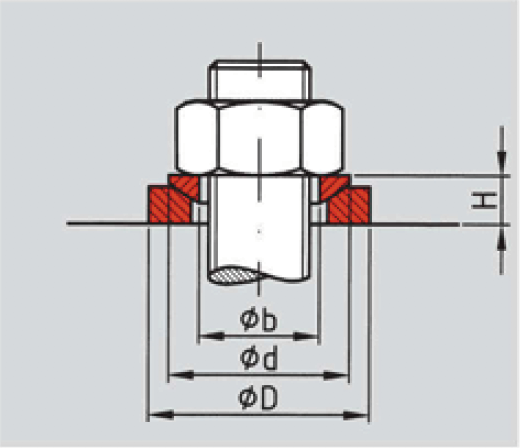
| S | ØD | H | Ød | Øb |
|---|---|---|---|---|
| I | 40 | 9 | 30 | 17 |
| II | 44 | 10 | 36 | 21 |
| III | 56 | 13 | 44 | 25 |
| IV | 68 | 16 | 56 | 31 |
| V | 78 | 20 | 68 | 37 |
r
Large spherical washer set for non-parallel bearing surfaces
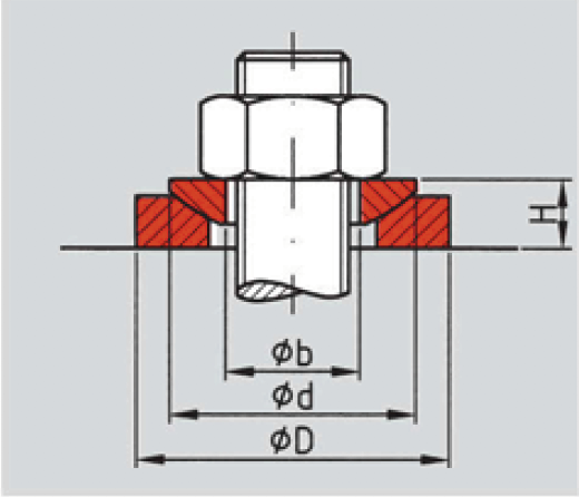
| S | ØD | H | Ød | Øb |
|---|---|---|---|---|
| I | 44 | 10 | 36 | 17 |
| II | 56 | 13 | 44 | 21 |
| III | 68 | 16 | 56 | 25 |
| IV | 80 | 16 | 56 | 31 |
| V | 100 | 20 | 68 | 37 |